Cross Sections
Version 3.6Cross Sections
The Cross Sections feature creates detailed cross-section views of individual SketchData components. It cuts through the middle of your selected components to reveal internal construction, hardware placement, and joinery details. Each cross-section is saved as a scene with a dedicated style optimized for viewing internal component details.
Requirements
- SketchData components (version 3 catalog items) selected in your SketchUp model
- A Design Tools license (this feature is not available in DEMO mode)
How to Use
From the Context Menu
- Select the specific SketchData component(s) you want cross-section views for.
- Right-click the selection and choose from the SD Elevations submenu:
- Cross Sections Left — Creates a cross-section view from the left side of each component.
- Cross Sections Right — Creates a cross-section view from the right side of each component.
- Cross Sections Both — Creates cross-section views from both the left and right sides of each component.
- Cross-section scenes are created immediately and appear in the Scenes panel.
- Scene names are based on the component name (e.g., "Base Cabinet Left", "Base Cabinet Right").
Settings Reference
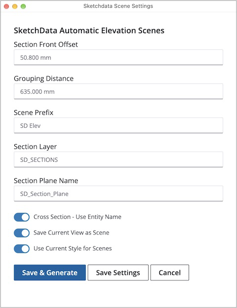
Cross-sections use several settings that are configured in the SketchData Automatic Elevation Scenes dialog (accessed via Extensions > SketchData > Generate Elevations):
Cross Section - Use Entity Name
- When enabled (default) — Scene names include the component's name, making it easy to identify which component each section belongs to. Example: "Wall Cabinet Left".
- When disabled — Scene names do not include the component's entity name.
Section Layer
- The layer where section planes are created. Default: "SD_SECTIONS".
- The layer is automatically created if it doesn't exist and is hidden by default.
Section Plane Name
- The name assigned to each section plane. Default: "SD_Section_Plane".
Tip: Open the Extensions > SketchData > Generate Elevations dialog to configure these settings. Click Save Settings to save them without generating elevations.
What Happens During Generation
- Each selected SketchData component is analyzed for its dimensions.
- All other entities in the model are temporarily hidden so only the component being sectioned is visible.
- A section plane is created cutting through the middle of each component from the selected direction (left, right, or both).
- A scene is created for each cross-section with the camera looking directly at the cut face.
- The "SD Cross Sections" style is applied, which includes section cuts and display settings optimized for viewing internal details.
- After all cross-sections are created, you are returned to your working view.
Using Cross-Section Scenes
- Navigate to a cross-section scene in the Scenes panel to view the internal details of a component.
- The view automatically zooms to show the full height of the section.
- Return to your normal modeling view by selecting your original scene (or "SD Default" if one was created during elevation generation).
Troubleshooting
Menu items are grayed out: Ensure you have a Design Tools license. Cross-sections are not available in DEMO mode.
No scenes created: Make sure you have selected SketchData version 3 catalog components before right-clicking. Standard SketchUp components or older SketchData items will not be processed.
Section cuts not showing: The feature automatically applies the "SD Cross Sections" style. If section cuts are still not visible, verify that the style is active and has Section Cuts enabled.
Want to see internal details of unselected components: Select the specific components first, then use the cross-section options. All other geometry is hidden during cross-section scenes to provide a clear view of the component internals.
If you have any questions or need assistance please contact support.